Handbells
// Published on Jan 13, 2026
Pictures
Summary
- Dirt cheap PCB modules for automating handbell playing for a club project.
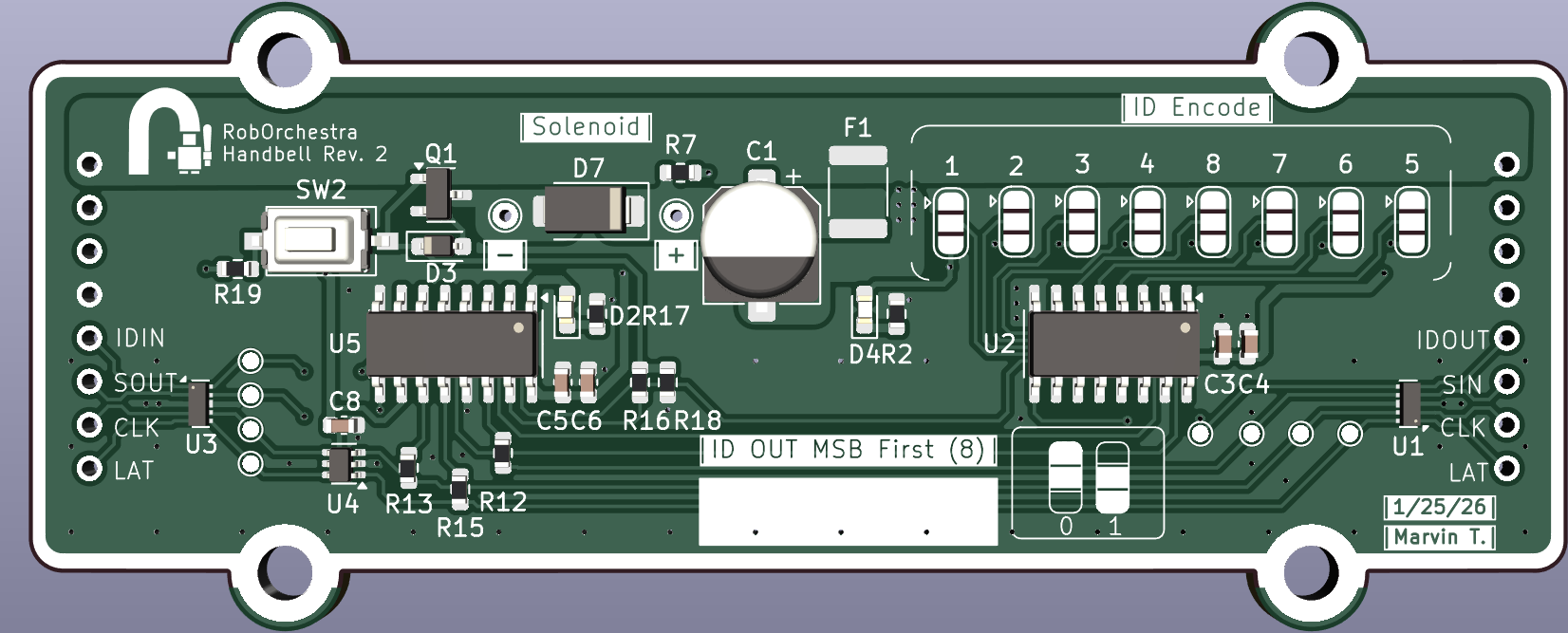
- Modular, daisy-chainable solenoid driver system for robotic handbells using magnetic pogo pins for assembly and hot-swapping
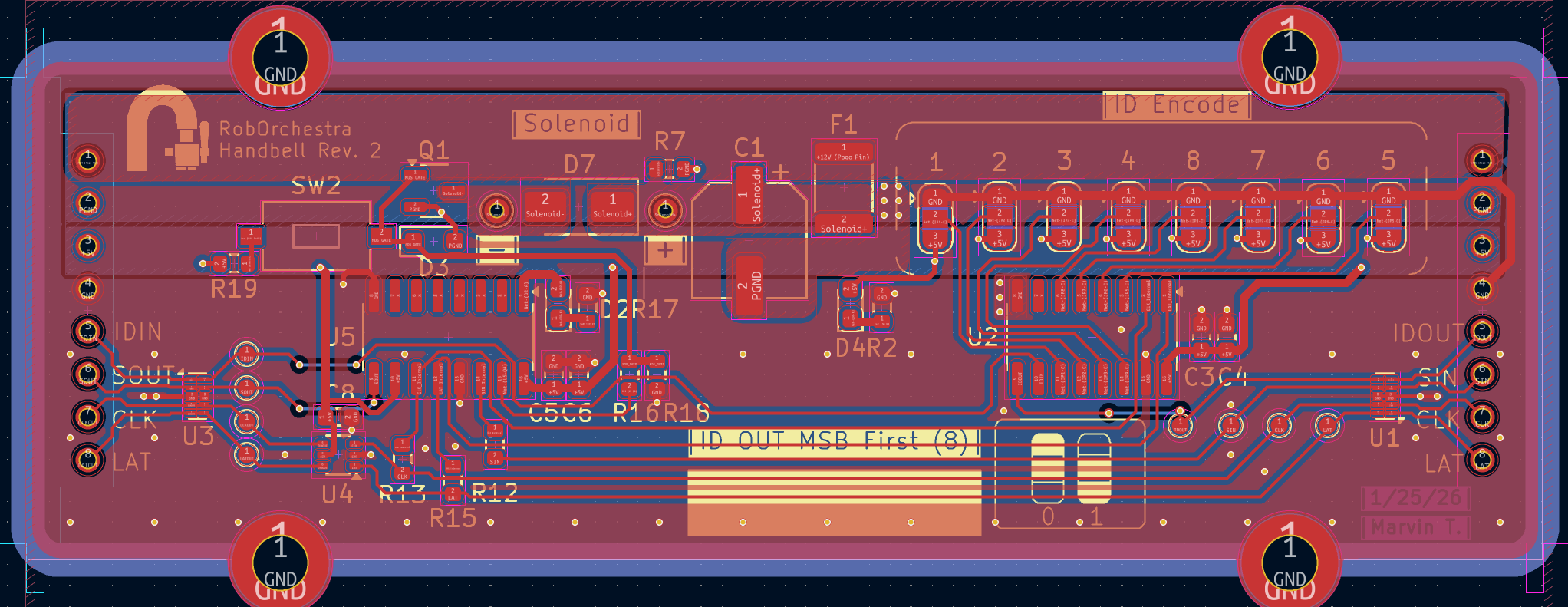
- Bidirectional shift register architecture using 74HC595s for actuation and 74HC165s for address reading, sharing clock and latch lines to minimize connector pin count.
- USBLC6-4SC6 TVS arrays and 750mA PTC fuses for localized fault isolation
- 2 layer PCB with split ground returns and bulk capacitance to mitigate noise from solenoids
Background
The goal was to automate a set of old handbells for RobOrchestra. Instead of a fixed frame, I designed a modular system where each bell is its own independent unit.
Mechanism: Solenoid actuation simulating a grand piano hammer action to strike the bell.
Interconnect: 8-pin magnetic pogo connectors allow for tool-free assembly. Users can snap up to 24 bells together in a single chain.
Scalability: The chain length is theoretically limited only by power drop. Rough estimation is 30 or so in one line before the 5V rail becomes 4.6V .
Transposition?: Remove a module. Your middle C is now a C#.
Logic
Each module acts as a node in a localized SPI-like bus. The design uses cheap ICs to maintain a “smart” chain without requiring a microcontroller on every board. Why? tight budget.
Output (SIPO): A 74HC595 shift register drives the solenoid and a status LED.
Input (PISO): A 74HC165 reads an 8-bit solder-jumper address, allowing the main controller to auto-detect which bell tone is plugged into which position in the chain.
Shared Clocking: Both logic chips share CLK and LAT lines to minimize the pin count on the pogo connectors.
Protection & EMI
Since these modules are designed to be handled constantly and hot-plugged, board-level protection was a primary design constraint.
**ESD: ** USBLC6-4SC6 TVS arrays are placed at both input and output pogo connectors to clamp static shocks from handling.
Overcurrent: Every module features a 750mA PTC Fuse. If a solenoid shorts or burns out, it isolates that specific node, allowing the rest of the stream to maintain functionality.
Manual Override: A button allows for manual firing. The button can physically override the logic chip’s output since it’s a 10:1 resistor divider that limits current (but allows for logic high).
Split Ground: To mitigate ground bounce from worst case 6A peak current, the solenoid ground is separated from the logic ground.
EMI: Digital signals are routed over a solid ground plane to ensure signal integrity across the long daisy chain.