100W USB-C PD Driver Board
// Published on Feb 10, 2026
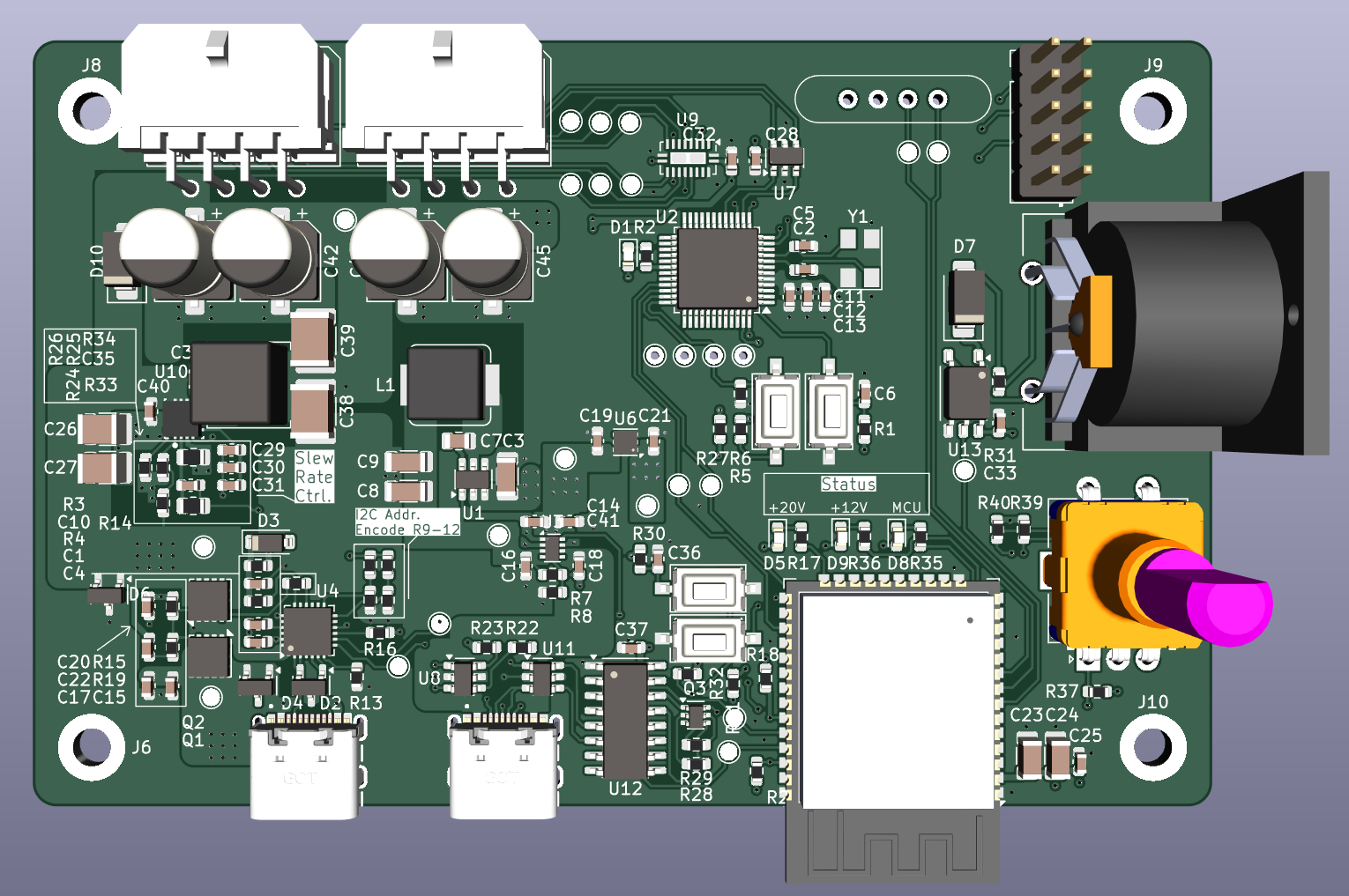
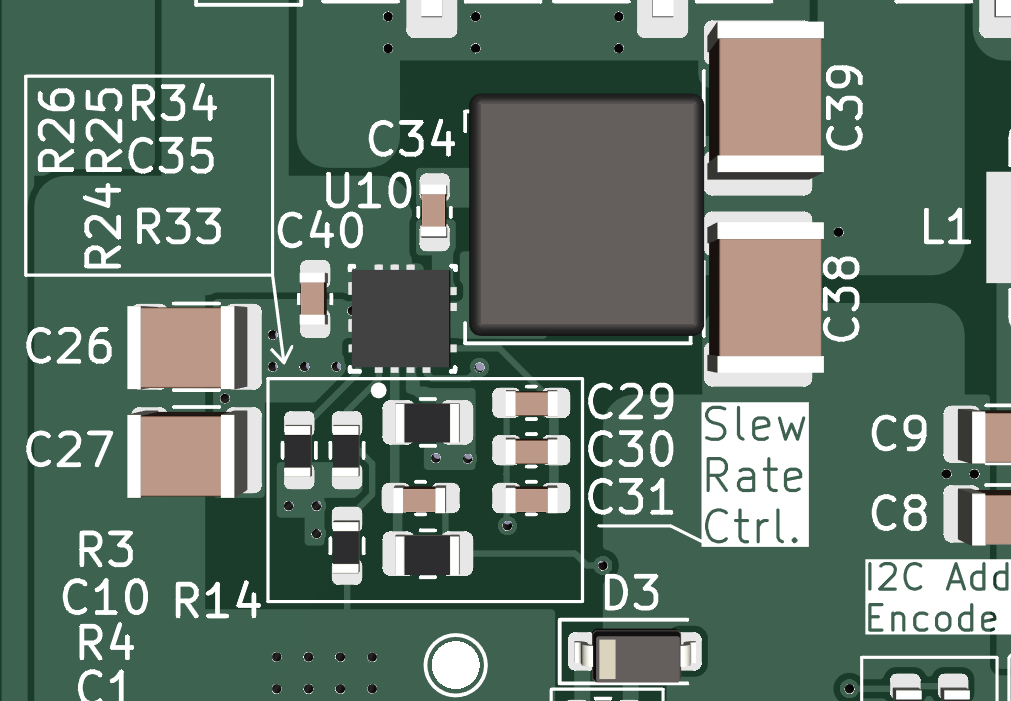
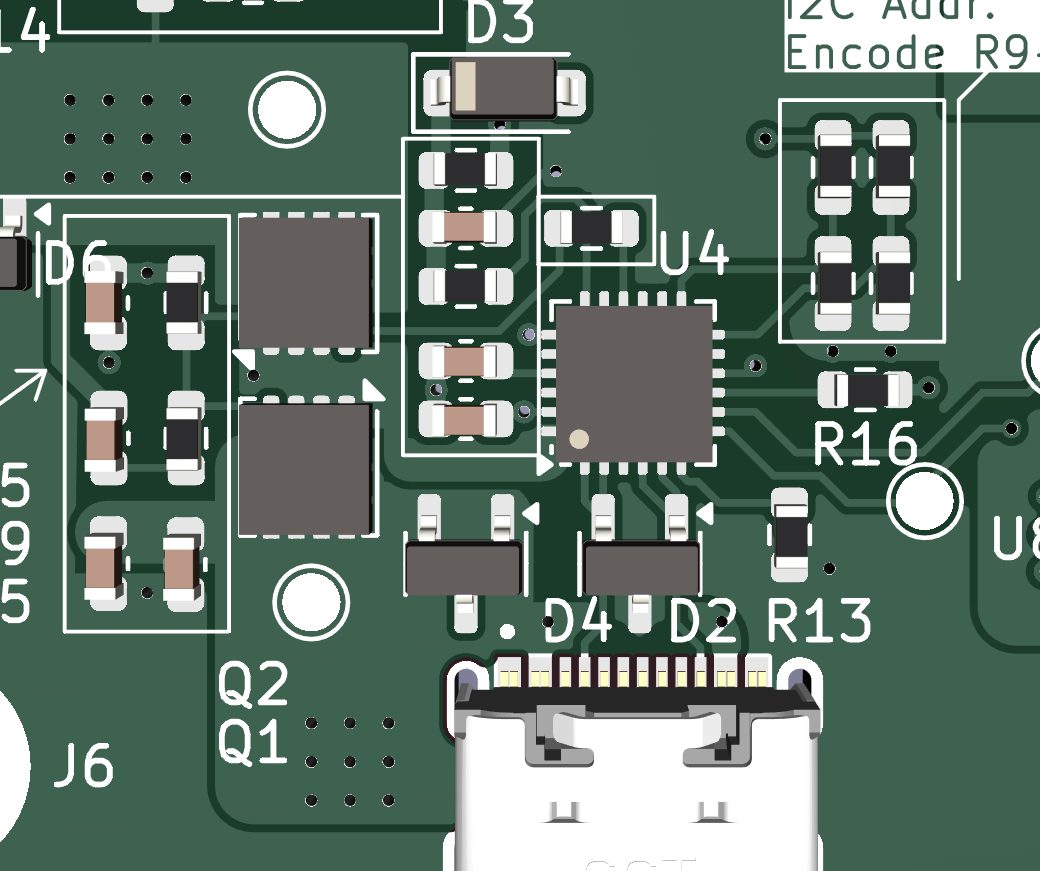
Pictures

Summary
- 4 layer PCB with SIG GND GND SIG stackup
- Dual MCU architecture (STM32G0 for control, ESP32 higher level communication)
- Multiple synchronous buck converters for split voltage rails
- Dual USB-C, split data and power delivery negotiation
- Power MUXing and MCU controlled power sequencing for safety
- Bulk capacitance backcurrent protection
- test points everwhere. they are free.
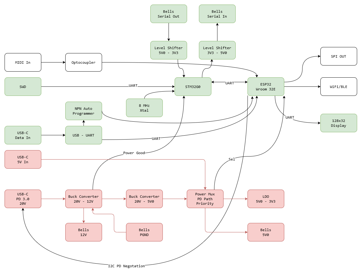
Block Diagram
Motivation
I realized early on that driving 24+ solenoids with good timing is a nightmare when you also want WIFI. The ESP32 is fast, sure, but WiFi interrupts can mess with things and I didn’t want the music to stutter just because we received packets.
I also needed power. I don’t like barrel plugs anymore after I fried something that was rated for 5V with a 9V jack.
Standard 5V USB wasn’t going to cut it either because it’s limited to maybe… 10W?.
So, this was the solution. USB-C power delivery negotiation so that the entire board could be powered by a laptop charger or anything that supplied 20V 5A.
The architecture relies on two MCUs and some specific power management ICs.
- ESP32-Wroom: Has built in PIFA and also a floating point unit (nice). It handles the “soft” real-time tasks: serving the web page, decoding MIDI, and calculating which bells need to fire.
- STM32G030: A dirt-cheap Cortex-M0. Drives the SPI chains using DMA. and communicates to the ESP32 with UART. I have experience with STM32 family chips, so this was an easy choice.
- STUSB4500: Negotiates 20V from the charger immediately upon connection.
- TPS2116: Power MUX IC that selectively prioritizes the main power USB rail. Prevents against brownouts and backfeed if only the data USB was plugged in.
- TLP2361: Optocoupler for the MIDI bus. I stuck to the standard DIN-5 pinout since we had some existing Arduino MIDI shield hardware from before my involvement. Built in for back compatibility.